Still having some issues with modeling the 3D solids.
Looks like I may have run into the limitation of the CAD software, so I need to find a way to work around it.
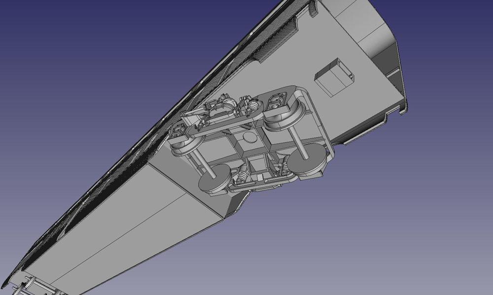
The good news is that preliminary testing (still only in CAD, mind you) shows that the trucks pivot unrestricted when put in place under the cars, so the minimum curve radius that the cars will handle should be very small.
He sure did, and their booth at the hobby shows is always lit up with all kinds of flashing and blinking and running lights on everything from 1:160 to 1:32.
On that YouTube channel there's a lot of example videos including "Tamiya scale" beacons.
The thing is - I have no experience with this, so I don't know if it's actually a good design.
I go with my gut feeling and try to make a model that is easy to deal with - even for an inexperienced modeler. That means I do take the time to search for alternative and maybe simpler solutions to problems.
Jens
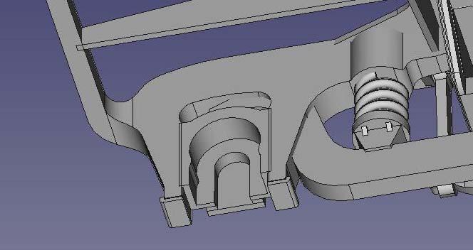
Edit: I'm told that the German manufacturer MBW is using the same scheme - albeit with tighter locking on the bearings - so it would seem I'm on the right path.
Makes me think maybe I should tighten the locks in the cutouts as it's easier to remove material than to add it.
It still needs some spit and polish and I need to have a look at why some of the parts act up in the CAD modelling. I also need to strip some material on the inside to optimise the price.
It hasn't been tested for printability at Shapeways, but I've kept all dimensions within their recommendations, so it can't be much off.
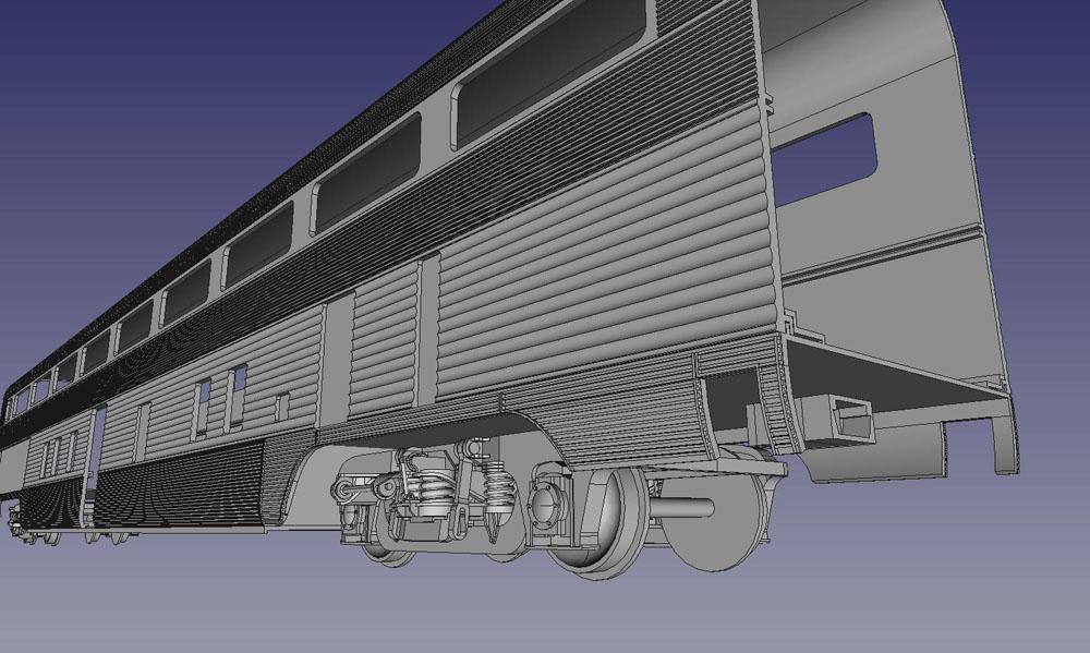
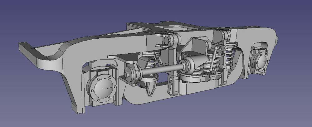
A bit more progress. Dang, it's beginning to look the part
I took the time to figure out the principle of the suspension, and then I needed to figure out how to make the model. Learning the features of FreeCAD as I go along ...
My preliminary design goal - and keep in mind I haven't measured or tested anything yet, as I'm still designing strictly off the drawings - is the European 1020 mm or 40 inch radius.
On the drawings, the truck frames are of course designed for prototypical wheel flanges. When using model wheels you need to extend the end crossbars a little to allow for the larger flanges. This may not be needed if you're using fine scale wheels, but using the wheels I picked - the NWSL #28671-4, I need to move the crossbars on the design away from the prototypical dimension. If you're using even larger flanges, you need to adjust for that.
This is actually bad news, because (I think) the larger flanges are typically used on layouts with sharper curves, and bigger truck frames restrict the movement of the trucks, and thus the minimum negotiable curves of the cars.
This can probably be mended somewhat by designing the truck frames for maximum movement between the skirts of the car, and I'll work on that eventually.
When I'm done, my plan is to provide the CAD file for the trucks as a download, so anyone can adjust to their particular like of wheels and bearings.
On the German gauge 1 forum there's a thread about Rail-Kees from Holland working on the SBB/NS type RAm TEE train.
The designer mentions a possibility of the Northlander version, which could be of interest to US/Canadian modelers. He also mentions the Northlander with an F7.


")
Santa Fe hi-level coaches
in Kitbashing & Model Making
Posted
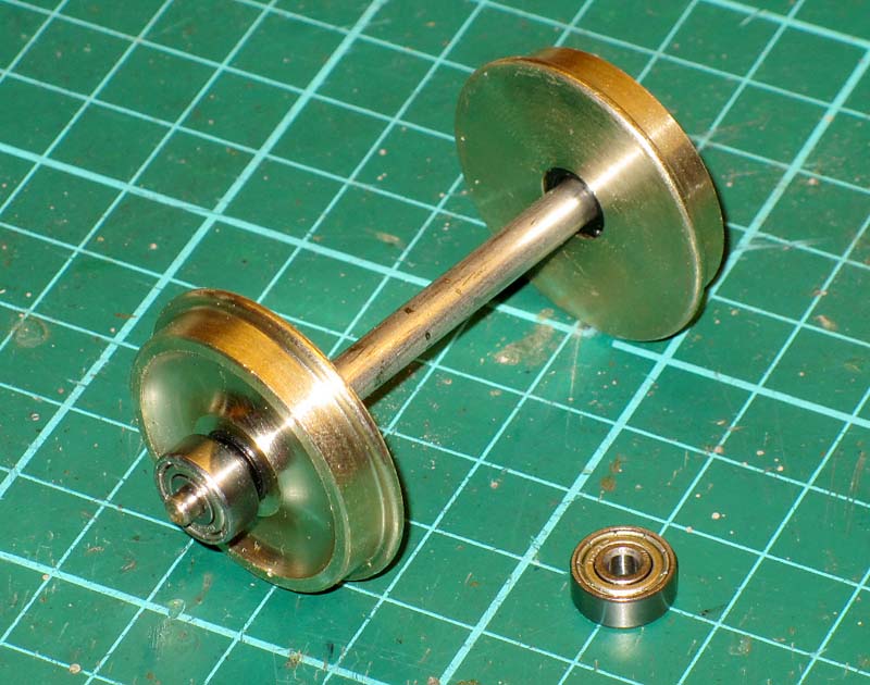
Here's the truck with bearings and NWSL wheels mounted and sitting on Märklin code 200 track.
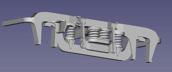
I haven't made up my mind yet, but look at the springs") and it rolls like a champ.
and it rolls like a champ.
Let's see when it gets a coat of paint and braces at the forks mounted ...
Jens