Hello guys. I am still kicken. Not doing anything, just taking it easy. Racing formula one cars on a PS5, almost like the real thing. Hope everyone is well. Bob.
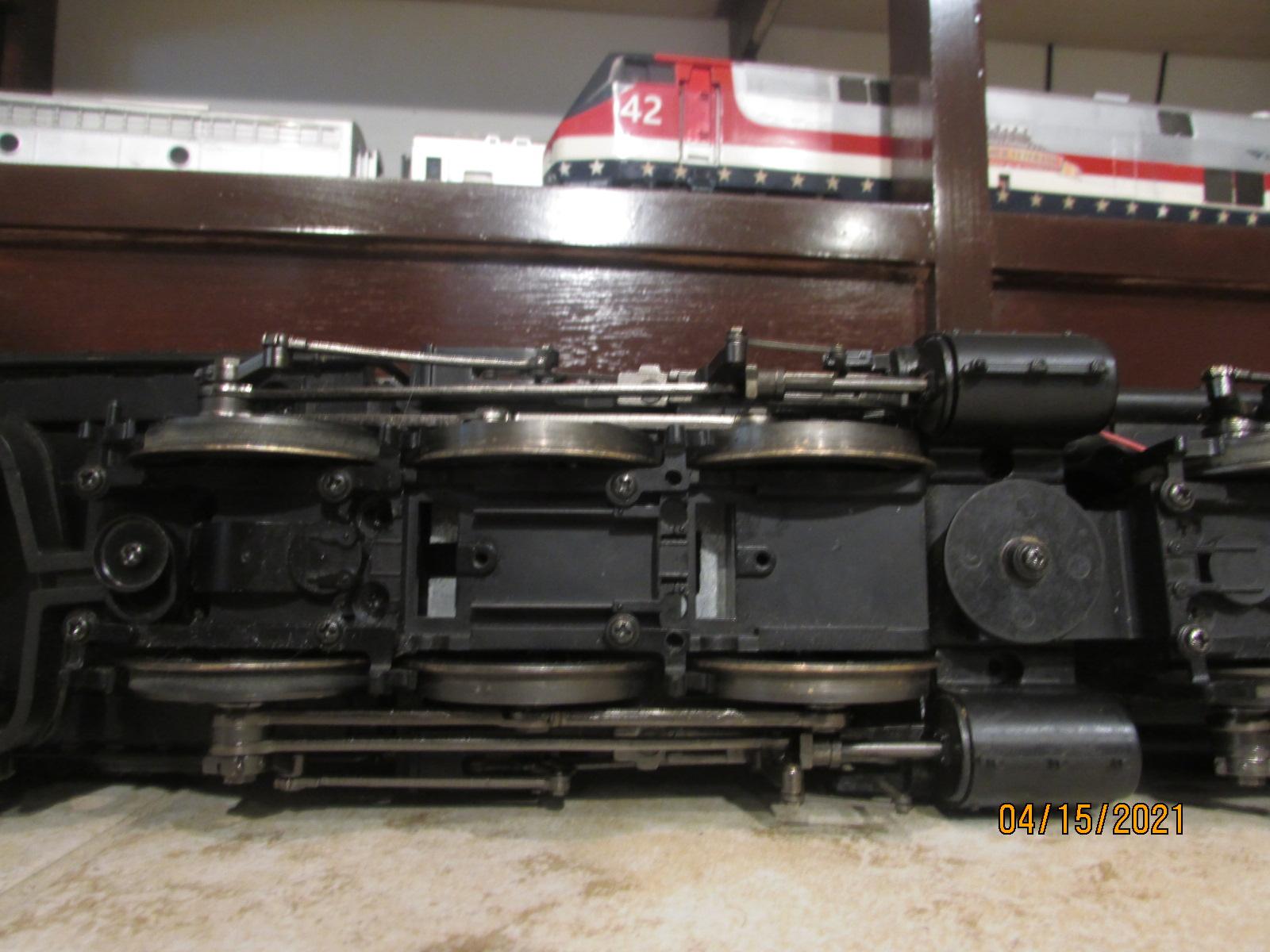
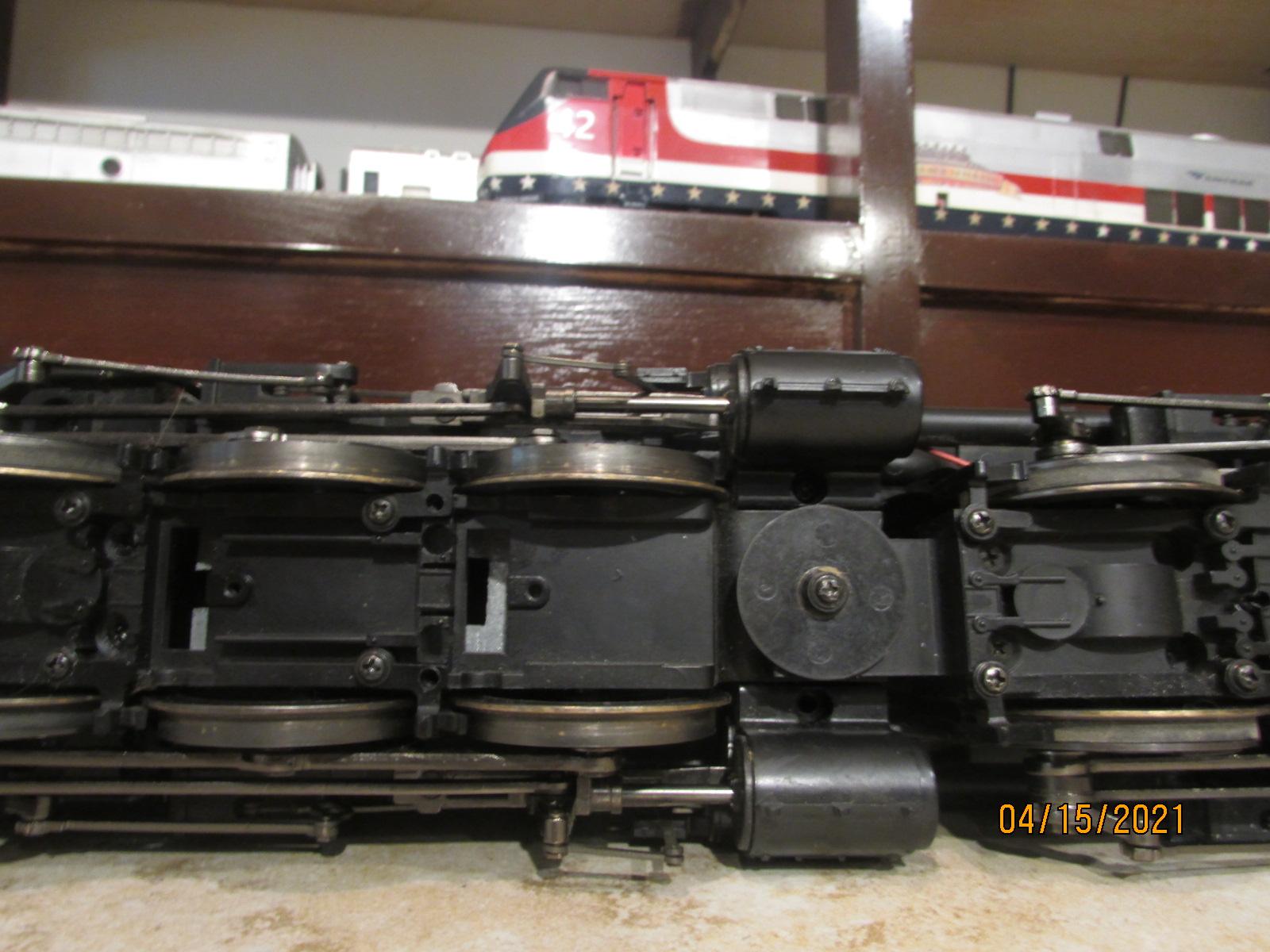
Need help on what kind of wipers are needed for this Challenger, push on or oring-loop with screw type, anybody know? If I am not aiming the camera in the right place, let me know. Thanks, Here are some pics. Bob.
I sold the Challenger and the person that bought it wants to run it with track power. Does anyone have a set of wipers for the Challenger? Thanks, Bob.
I picked up the Fine Arts Models PRR sleeper on Ebay that was damaged, had to pay 550.00, but worth it, damage is not bad at all., Couple of diaphrams and will look like new. Bob
Yes it is difficult to find much useful info. about these engines, especially about running them because most end up on the shelf. Probably, it would be OK on a 20 ft. radius, but not ten. I will keep grinding until it makes it around my layout if there is enough left to run. Bob.
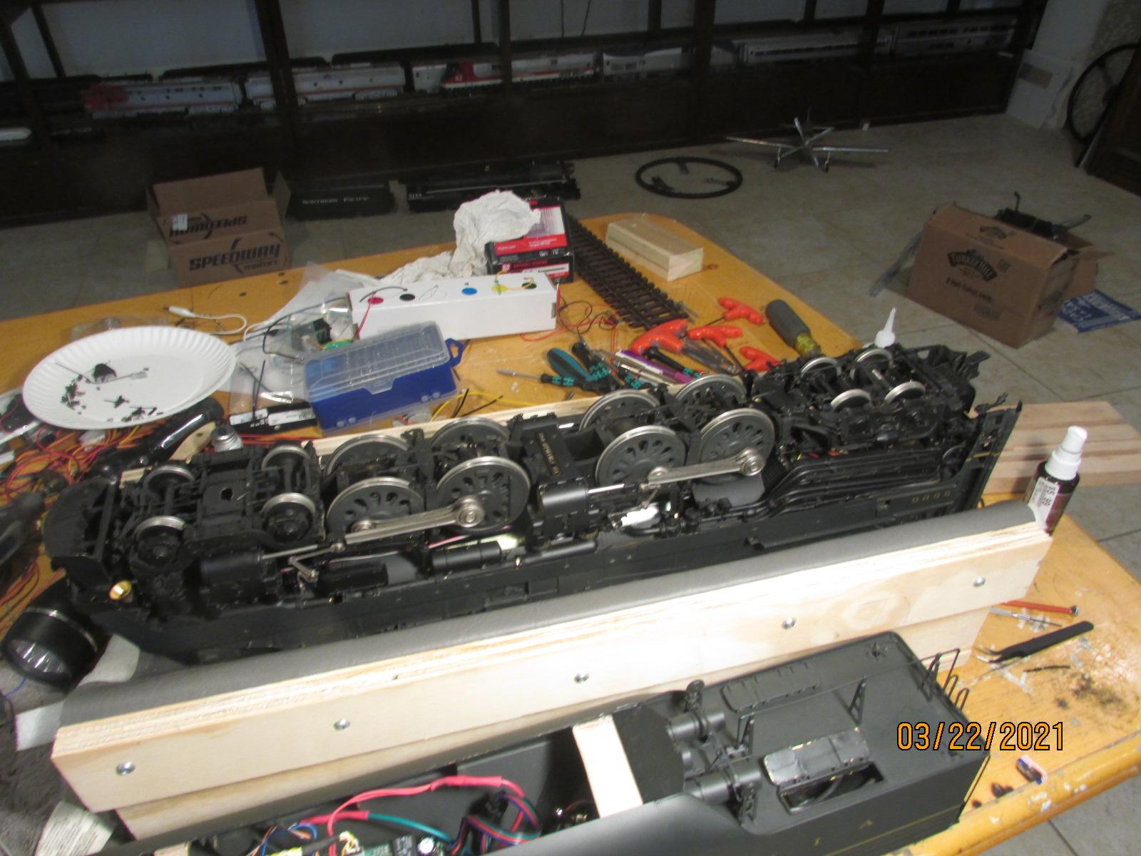
Disaster has struck. There is no way that this T1 will negotiate these curves. So, I have to shave some drive wheel flanges. The question is, do I make this engine a shelf queen?, or do I alter it to be able to use it on the layout. I am starting out with one set of wheel flanges and if need be, I might have to shave two sets of wheel flanges, I will know more later today. Bob.
Well, just like the prototype T1, this FAM is no different. This model is a replica of the prototype and is not made for 10' radii. So, the lead and trailing truck won't make the tight turns as designed. I had to mill the pivot holes in both the lead and trailing trucks laterally so that they were a little sloppy and able to make the turns. The lead truck is done and I'm working on the trailing truck, this brass is a little tougher than plastic. I will let you know when I get it running around the curves. Bob.
Hey Chuck. Do you know what those 16 numbers mean? Does it mean 16 lines on the tach flywheel?, or does it mean 16 revs on the drivers? If you know, I would like to know. Bob.
Ray, have they change the program in the Iphone for the Explorer? The engine was recognized, and ran fine before I changed over to a different loco, and now the Explorer won't recognize my engine. Now, I might have not wired it correctly, and I am working on that now, will know more tomorrow. This an upgraded PS-3 and does it work on 5g? I am all messed up. Bob.
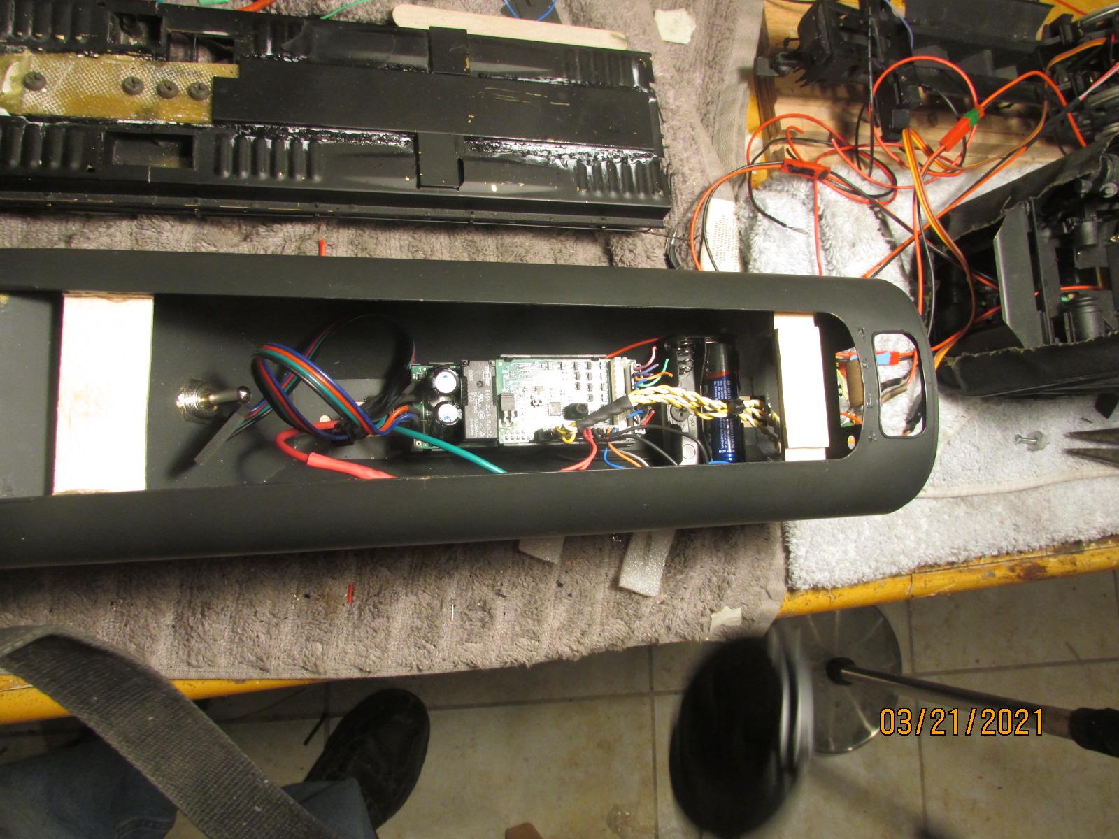
I am using the explorer for two reasons, one is I don't have to drag a TIU car around, and the other, I wanted to install everything in the tender so that if anything should happen to the sound card, I wouldn't have to tear the loco apart, too much work. It is easy to opern up the tender, six screws. Bob.
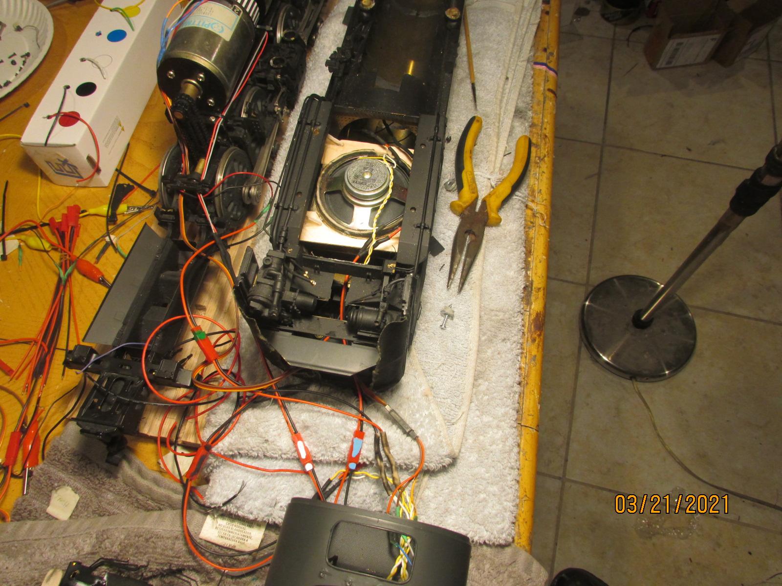
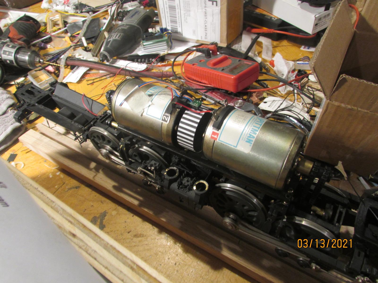
Thanks Sean. I will be installing volt-amp meters in the engine so that I can better assess what's happening with the current draw, if I can figure out how to wire them, plenty of examples on YouTube. I have even thought of putting a switch in the tender so that I can run both motors or just one, but it depends on how much drag that would produce with only one running, we shall see. Well I be wiring all day today, if I can figure out where all of the wires go. Bob.
Yes the flywheel was already installed. I don't like working on brass models, everything is in the way. They went to extra lengths for detail. They place parts that you can't see for the sake of detail. They even modelled the auger for coal movement in the coal car that is out of sight under a shroud. I wouldn't even known it was there if I hadn't had to remove it to install some of the electronics. One thing that was interesting. The tender's floor was made of two pieces and soldered in the middle and the solder failed, duh. It was if they ran out of a full sheet of brass and made it in two pieces. They butt soldered the pieces together and was doomed to failure and I had to make a repair and reinforce it. I did find out one thing, super glue works on brass. I might remove one of the motors since it is battery powered and don't want the higher current draw of two motors. These motors are so overkill that it won't know the difference. I am going to compare the amps with either one or two motors and make my decision then. These brass engines are not made for everyday running, parts are easily bent and have to be straightened and then eventually break off. Buyers of these brass engines usually don't even take it out of the box and place them on the shelf hoping that the price will go up, well that hasn't happened. It will be interesting as to what the current draw is on these two behemoth motors. One other interesting thing was the how they picked up the pulses for the chuff sounds. It was designed with two independent four lobes on two different axles. The motors are not joined at the shaft, so the electronics picks up two separate pulse generations for the chuff cycles of each motor. It would have provided a more realistic chuff sound especially of one set of drive wheels slipped as it did in real life. Bob.
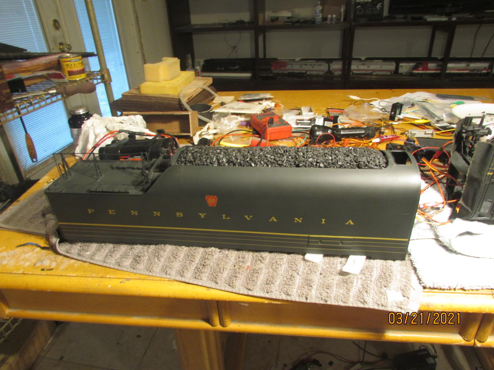
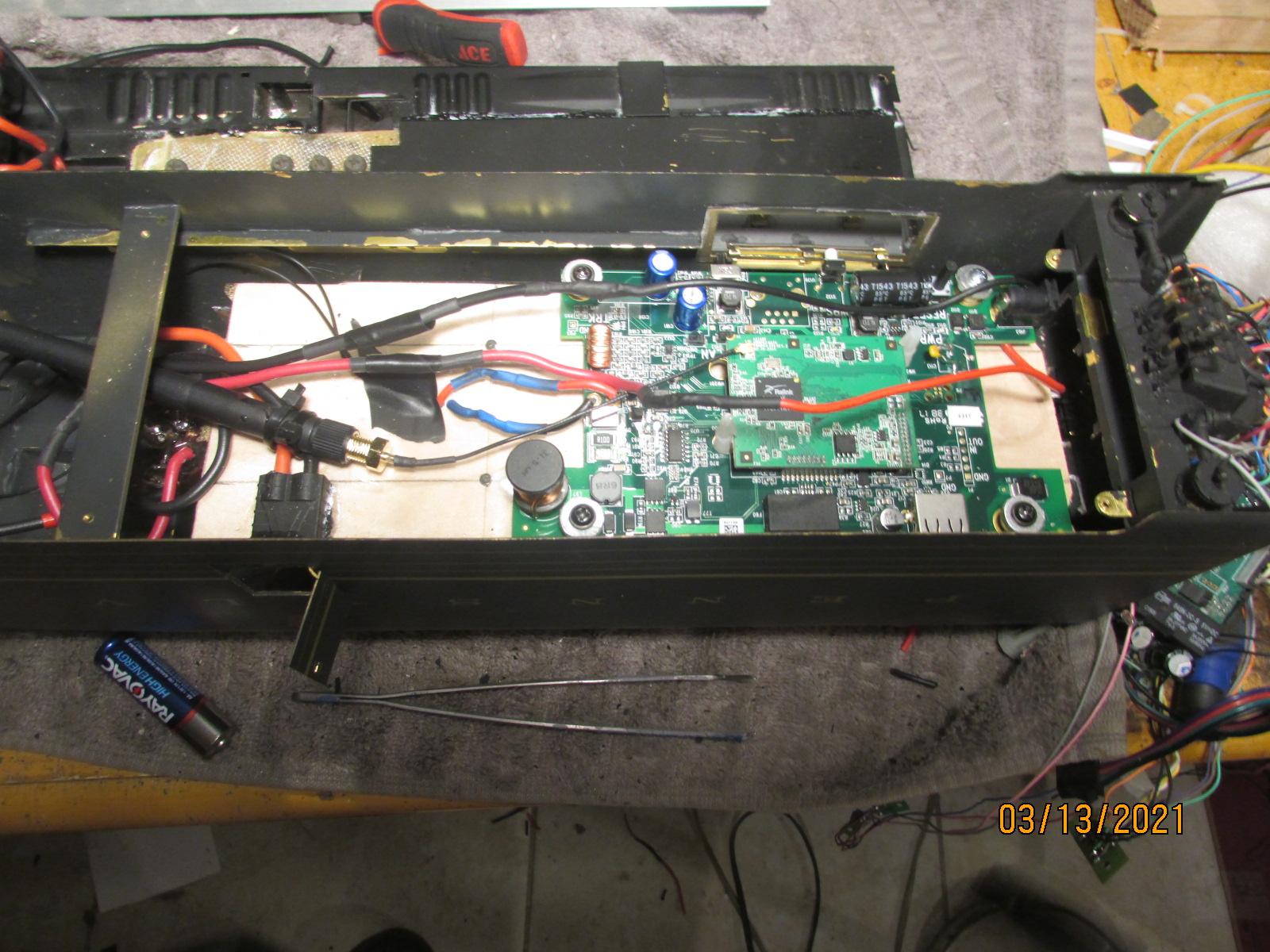
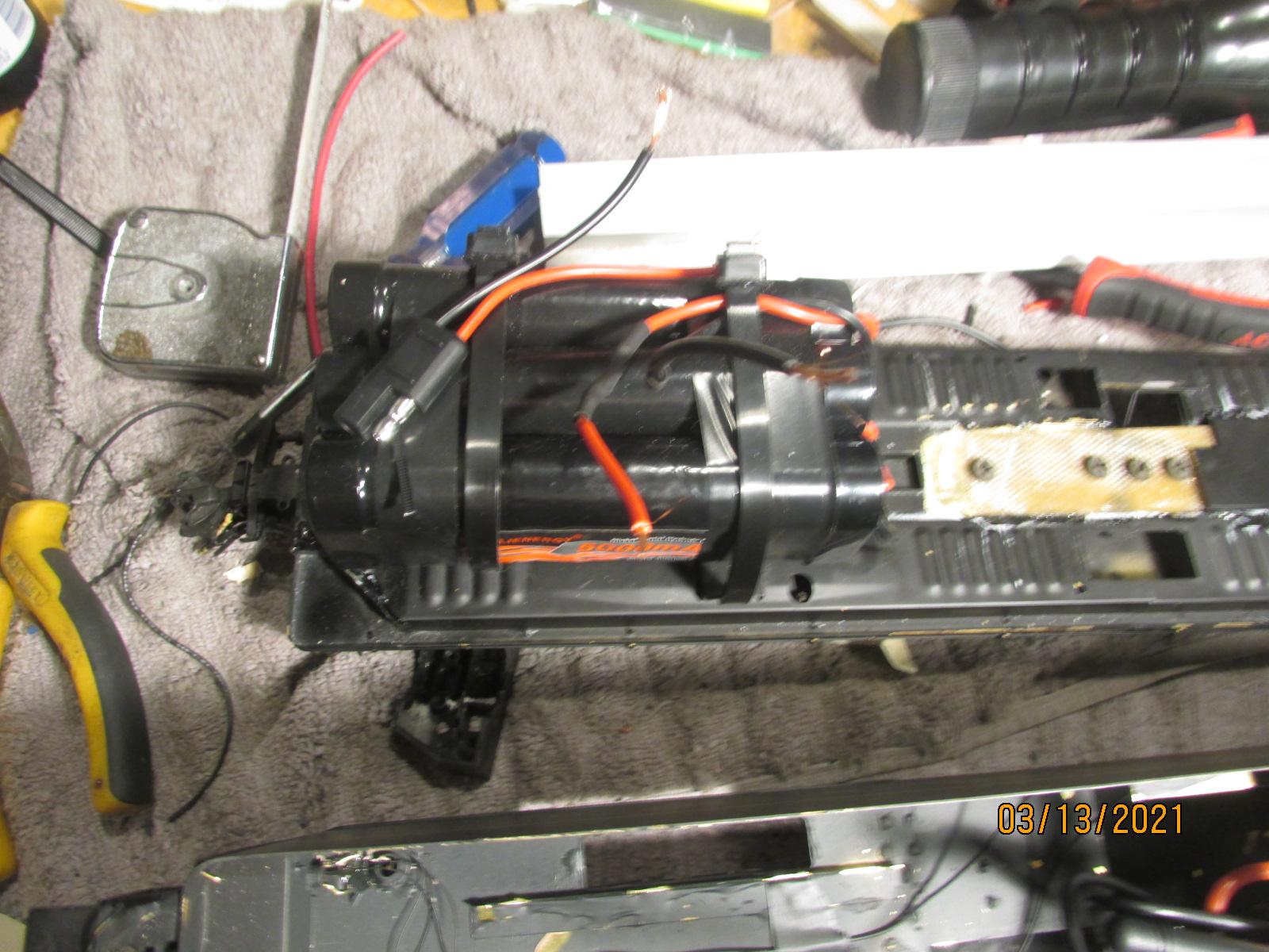
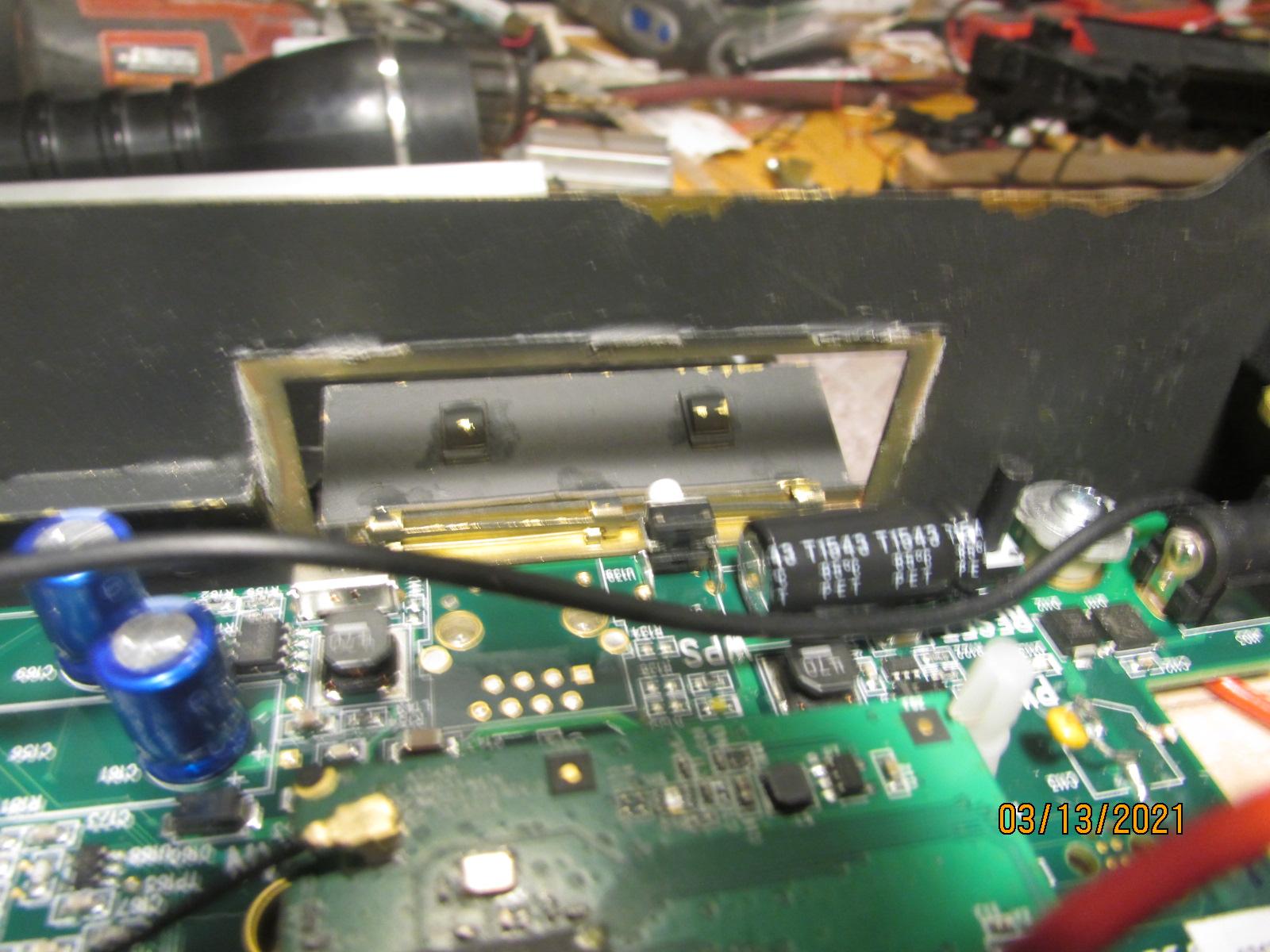
Installing PS-3 into a FAM T1. I am installing everything into the coal car because I never want to take the loco apart again, a nightmare. The only thing that will go into the engine is the speaker and lights. The explorer unit fits well because the switches are in the correct spot for the doors in the tender. Also there is a door for the charge plug. I will show you the topside of the tender tomorrow where I will be installing the sound card and the light aux. card. Bob.
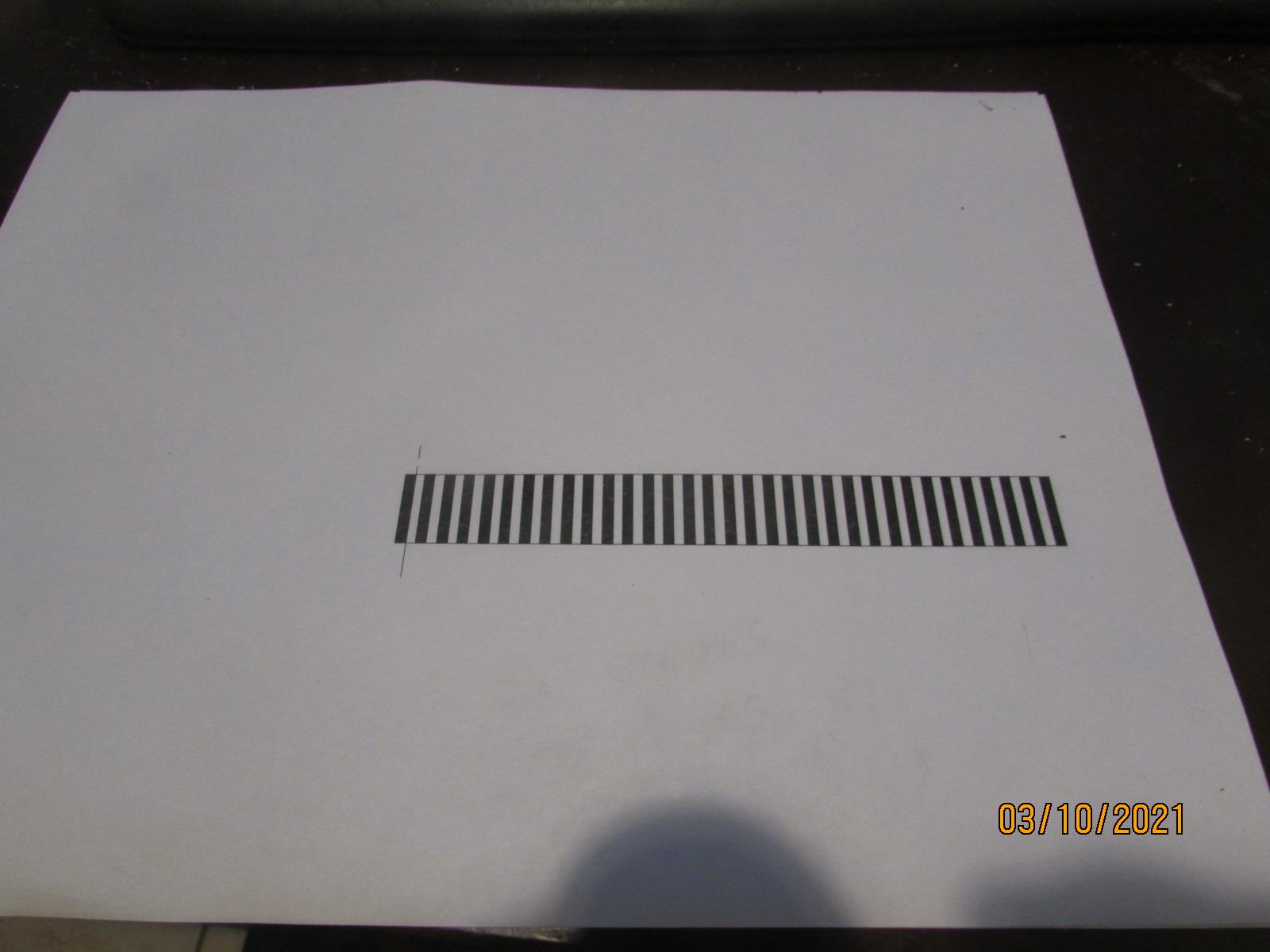
I am switching the complete sound system from one loco to another. The gear ratios are different. The original loco ratio is, 11:1, and the target loco ratio is 8:1. The number of pulses required for one cycle of chuffs, (one rev. of the wheel) is 275. 25 black lines times 11=275. To transfer this cycle to a loco with a ratio of 8:1, the same number of pulses is required, so 275 pulses divided by the new ratio of 8:1=34. So, the new strip of lines will have to have 34 lines instead of 25 to achieve the correct cycle of chuffs per one rev. I printed out 68 spaces therefore 34 lines. The circumference of the new flywheel is 5.4 inches, so the 34 lines had to be arranged within the 5.4 inches. If anyone has any info. that I missed, feel free to comment. Here is a picture of the strip. Bob.


1:32 scale Superliner passenger cars
in Rolling Stock
Posted
Hello guys. I am still kicken. Not doing anything, just taking it easy. Racing formula one cars on a PS5, almost like the real thing. Hope everyone is well. Bob.